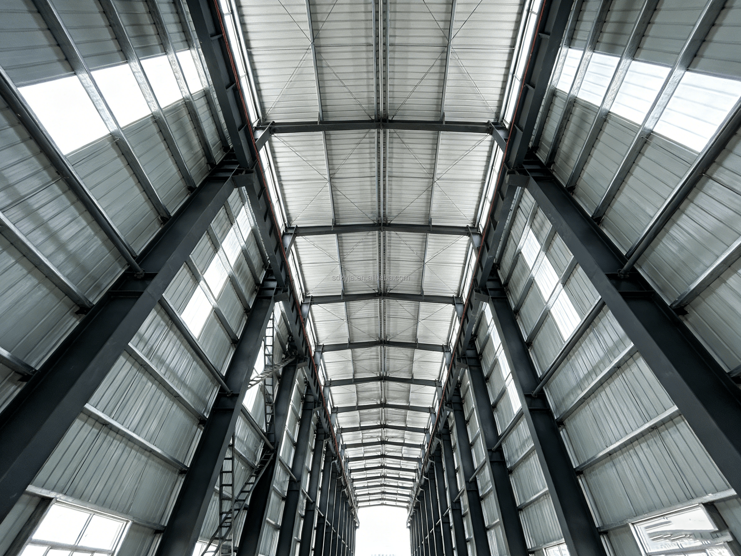
Home » News & Blog » How to Choose the Right Steel Structure Workshop Span, Height, and Crane Load
How to Choose the Right Steel Structure Workshop Span, Height, and Crane Load
Views: 0 Author: Site Editor Publish Time: 2026-09-10 Origin: Site
Miscalculating structural dimensions in industrial construction carries massive financial and operational risks. Retrofitting a building for a heavier crane or higher clearance often exceeds the cost of an entirely new build. Facility planners and project managers constantly struggle to balance immediate operational workflow requirements with site limitations and long-term scalability. You cannot afford to guess on dimensions when dealing with heavy steel construction.
Before committing to a manufacturing contract, you need a systematic evaluation framework to finalize the three most critical structural variables: span, height, and dynamic load capacity. Every inch of clearance and every ton of load capacity directly impacts the engineering requirements of the foundation, columns, and roof trusses. This guide breaks down exactly how to architect these specifications to ensure your steel structure workshop meets both current production demands and future expansion needs without unnecessary over-engineering.
Key Takeaways
Span dictates interior flexibility vs. cost: Clear spans maximize unobstructed floor space but increase steel tonnage costs exponentially beyond 30 meters, making multi-span configurations more viable for massive footprints.
Height requires clearance mapping: Eave height must account for the maximum hook height of overhead cranes plus the physical depth of the crane bridge and roof trusses, not just the height of the equipment on the floor.
Crane loads change the entire structural math: Integrating a crane system shifts design requirements from static load bearing to dynamic stress management, requiring specialized column reinforcements and engineered crane beams.
Custom design prevents over-engineering: Leveraging site-specific environmental data (wind, snow, seismic) alongside operational needs ensures you only pay for the steel tonnage required for safety and compliance.
Material selection impacts lifecycle ROI: Choosing the correct steel grades, thicknesses, and corrosion-resistant coatings minimizes maintenance and extends the facility's operational lifespan.
Establishing Baseline Success Criteria for Your Steel Structure Workshop
Successful industrial construction begins long before the first piece of steel is cut. You must establish strict baseline criteria based on how the facility will actually operate day-to-day. This requires mapping out the physical movement of assets and understanding the exact limitations of your chosen construction site. Skipping this phase leads to permanent operational bottlenecks.
Defining Operational Workflow
The foundational footprint of your building is dictated entirely by internal logistics. You must map out the movement of raw materials from the receiving dock to the production line, and finally to outbound shipping. Machinery layout requires precise spatial planning. Heavy stamping presses, CNC machines, or assembly lines need specific clearances not just for operation, but for routine maintenance and part replacement.
Consider your material handling equipment. A heavy-duty forklift carrying 40-foot steel beams requires a massive turning radius. If your aisle spacing is off by just a few feet, that forklift will inevitably collide with your storage racking systems or structural columns. You must also account for the concrete slab-on-grade requirements. Heavy machinery induces severe point loads on the floor, requiring thicker concrete and heavier rebar reinforcement in specific zones. Failing to account for these workflow dynamics results in a facility that actively fights against your production goals.
Site Selection and Pre-Construction Planning
Early site selection heavily influences structural design. You cannot finalize building dimensions without comprehensive soil testing. Geotechnical reports determine the soil's bearing capacity, which directly dictates foundation requirements. Poor soil conditions might require deep pile foundations, massive spread footings, or extensive chemical soil stabilization. These foundation upgrades alter the entire project timeline and budget.
Geotechnical Soil Boring: Drill test holes across the site to identify soil strata, water table levels, and bedrock depth.
Topographical Surveying: Map the exact elevation changes across the property to determine grading requirements and retaining wall necessities.
Utility Mapping: Locate all underground water, gas, and electrical lines to ensure foundation piers do not intersect with existing infrastructure.
You must map out a pre-construction timeline that aligns perfectly with off-site manufacturing schedules. Steel fabrication happens concurrently with site grading and foundation pouring. Any delay in finalizing the anchor bolt layout will halt steel production and delay the entire assembly phase.
Site Constraints and Zoning
Property lines and local zoning laws impose hard limits on your building's physical dimensions. You must evaluate property line setbacks, which dictate how close the building can sit to the edge of the lot. Local height restrictions often cap the maximum peak height of industrial buildings, forcing engineers to adjust roof pitches or lower eave heights to comply.
Topographical challenges, such as significant elevation changes across the build site, require stepped foundations. A stepped foundation means your steel columns will have varying base elevations, requiring custom fabrication lengths for every column along that wall. These constraints must be identified before drafting preliminary structural dimensions.
Environmental Load Baselines
Local building codes establish the absolute minimum load requirements your structure must withstand. These are categorized into dead loads and environmental live loads. Dead loads include the permanent weight of the structure itself, roofing materials, insulation, and fixed mechanical systems.
Environmental live loads depend entirely on regional climate and geography. Engineers must calculate snow accumulation, which adds massive downward weight to the roof. They must account for wind uplift, which attempts to tear the roof off and push the walls inward. Seismic activity introduces violent lateral shear forces that require heavy cross-bracing. These environmental baselines must be established before any internal operational loads are added to the engineering model.
Determining the Optimal Span for a Large Span Steel Workshop
The span of your building determines the internal layout flexibility. Choosing the right span configuration is a critical balance between unobstructed floor space and the sheer weight of the steel required to support the roof. When designing a large span steel workshop, the engineering focus shifts heavily toward managing roof deflection.
Clear Span vs. Multi-Span Configurations
A clear span design features no interior support columns. This configuration is absolutely necessary for facilities like aircraft hangars, large-scale assembly lines, or heavy logistics hubs where interior columns would obstruct the movement of massive components. However, clear span structures face a distinct cost inflection point.
Once the width exceeds 30 to 40 meters, the required depth and thickness of the roof rafters increase exponentially to prevent sagging. The rigid frames must be fabricated with deep, tapered webs at the haunch (where the column meets the rafter) to handle the massive bending moments. This drastically increases the overall steel weight and shipping costs.
Introducing a single row of interior columns creates a multi-span configuration. This single change drastically reduces the required steel tonnage for the roof structure. By breaking the roof span into two or more smaller segments, engineers can use significantly lighter rafters. If internal pipe columns do not impede your operational workflow, a multi-span setup is always the more efficient choice for massive footprints.
Structural Feature
Clear Span Configuration
Multi-Span Configuration
Interior Columns
None. Provides 100% unobstructed floor space.
One or more rows of internal support columns.
Ideal Use Case
Aircraft hangars, large assembly lines, sports arenas.
Warehouses, distribution centers, standard manufacturing.
Steel Tonnage
High. Requires massive, deep roof rafters for wide widths.
Low to Moderate. Roof loads are distributed to interior columns.
Maximum Economical Width
Typically 30 to 40 meters before costs escalate sharply.
Virtually unlimited, depending on column spacing.
Foundation Requirements
Massive exterior footings to resist high overturning moments.
Smaller exterior footings, supplemented by interior pier pads.
Cost-to-Width Trade-offs in Steel Structure Custom Design
The relationship between building width, overall length, and bay spacing dictates the structural efficiency of your steel structure custom design. Bay spacing is the distance between the primary rigid frames along the length of the building. Standard economical bay spacings typically range from 6 meters to 9 meters.
Deviating from these standard increments impacts the sizing of secondary framing members like purlins (roof supports) and girts (wall supports). Wider bay spacing requires heavier, deeper purlins to bridge the gap between main frames. If you push a bay spacing to 12 meters, standard cold-formed Z-purlins will fail under the load. You will be forced to upgrade to heavy open-web steel joists, which offsets the savings of using fewer primary columns.
Future expansion must also be engineered into the initial design. If you anticipate lengthening the facility in the future, you must design the end-walls as expandable frames. Standard end-walls use lighter post-and-beam construction that cannot support the load of an additional building bay. Specifying an expandable rigid frame at the end-wall allows you to simply remove the exterior cladding and bolt on new structural bays without demolishing the existing framework.
Calculating Eave Height and Internal Clearance
Height is often the most misunderstood dimension in industrial construction. Specifying a building height based solely on the tallest piece of equipment on the floor will result in a facility that is functionally useless. You must calculate height based on dynamic operational clearances and overhead utility integration.
Equipment Clearances and Storage Racking Needs
You must first understand the distinction between eave height and peak height. Eave height is the measurement from the finished floor to the intersection of the sidewall and the roof. Peak height is the highest point of the roof in the center of the building. Eave height is the limiting factor for perimeter clearance. If you plan to install tall pallet racking or operate large machinery near the exterior walls, the eave height must accommodate those dimensions.
Vertical mapping requires a strict formula. You must calculate the maximum height of your stationary equipment, add the maximum extension limits of your forklift masts, and then add required safety clearances for overhead utilities. Suspended HVAC ductwork, high-bay LED lighting fixtures, and ESFR fire suppression sprinkler systems all hang below the roof rafters. If your eave height does not account for the depth of these utility systems, your material handling equipment will collide with them during daily operations.
Measure the tallest piece of stationary machinery, including any top-mounted exhaust stacks or maintenance access hatches.
Determine the maximum vertical reach of your tallest forklift or reach truck.
Calculate the drop depth of overhead utilities (HVAC ducts, radiant heaters, sprinkler pipes).
Add a minimum 1.5-meter safety buffer between the highest moving equipment and the lowest hanging utility fixture.
Integrating Roof Pitch and Climate Considerations
Roof pitch directly affects interior volume, heating and cooling efficiency, and structural performance. A standard low-pitch roof, such as a 1:12 pitch (rising 1 inch for every 12 inches of run), minimizes the total interior volume of the building. This reduces the amount of cubic air space that must be heated or cooled, lowering long-term utility expenses. However, a low pitch provides less vertical clearance near the center of the building compared to a steeper pitch.
Climate drives roof pitch adjustments. Regions that experience heavy winter snowfall require steeper roof pitches, such as 1:10 or 1:8, to help shed snow weight naturally. If snow accumulates on a low-pitch roof, the structural dead load increases massively. Engineers must then specify thicker roof panels and heavier rafters to prevent roof collapse. Altering the roof pitch inherently changes the interior clearance profile, meaning your vertical mapping calculations must be adjusted accordingly.
Engineering for Steel Workshop Load Bearing Capacity and Crane Systems
Industrial facilities are subjected to forces that standard commercial buildings never experience. The structural framework must be engineered to handle constant movement, vibration, and heavy lifting. This requires a deep understanding of how different loads interact with the steel skeleton.
Static vs. Dynamic Loads in Industrial Facilities
Engineers categorize forces into static and dynamic loads. Static loads remain constant over time. These include structural dead weight, suspended HVAC rooftop units, and fixed interior mezzanines used for office space or lightweight storage. Static loads are predictable and relatively simple to calculate using standard structural engineering formulas.
Dynamic loads change constantly in magnitude and location. These include vibrations from heavy stamping machinery, the movement of internal vehicles, and the live operational weight of overhead lifting equipment. Dynamic loads require stiffer frame designs. To prevent lateral sway and structural fatigue caused by these moving forces, engineers must integrate heavier bracing systems. X-bracing in the walls and roof, or rigid portal frames in areas where X-bracing would block doorways, are mandatory to maintain the steel workshop load bearing capacity.
Sizing the Steel Workshop Crane Beam and Support Columns
Integrating an overhead bridge crane changes the entire structural math of the building. The facility must support the dead load of the crane bridge and hoist itself, plus the maximum live load of the lifting capacity. Furthermore, the building must resist the longitudinal braking forces when the crane stops moving down the runway, and the lateral forces when the trolley moves across the bridge.
The engineering behind the steel workshop crane beam requires absolute precision. These runway beams must meet strict deflection limits, often L/600 or stricter, to ensure the crane travels smoothly without binding on the rails. To transfer these massive dynamic loads safely to the foundation, engineers utilize stepped columns or heavy welded corbels.
Stepped columns feature a wider lower section specifically designed to support the crane beam directly, separating the crane load from the roof load. This prevents the building frame from twisting under heavy lifts. The alignment of these columns during erection must be flawless. If the span between the runway beams varies by more than a few millimeters, the crane wheels will grind against the rails, causing premature wear and potential derailment.
Impact of Crane Tonnage on Structural Economics
The tonnage and duty cycle of your crane dictate the structural economics of the entire project. A 5-ton maintenance crane used once a week requires minimal structural upgrades. The existing primary frames can often support this load with standard bracket additions. However, a 50-ton continuous-use production crane requires a fundamentally different building design. The columns must be massively oversized, and the foundations must be engineered with deep concrete piers and heavy anchor bolt templates to resist overturning moments.
High-cycle cranes introduce the risk of metal fatigue. A crane that operates continuously for multiple shifts per day over a 20- to 50-year lifespan will subject the steel connections to millions of stress cycles. This necessitates heavier gauge steel, specialized moment connections utilizing slip-critical bolts, and rigorous non-destructive testing (NDT) of all structural welds during fabrication to ensure no microscopic cracks exist that could propagate under continuous vibration.
Balancing Cost, Scalability, and Implementation Risks
Optimizing your facility requires balancing upfront material costs with long-term durability. Attempting to cut corners during the engineering phase often results in catastrophic structural failures or massive maintenance liabilities down the road.
Value Engineering vs. Dangerous Cost-Cutting
True value engineering involves selecting the right materials for the specific application. Upgrading from standard carbon steel, like ASTM A36 with a 36 ksi yield strength, to high-strength steel, like ASTM A572 Grade 50, allows engineers to reduce the overall thickness of the steel webs and flanges. This reduces the total steel tonnage and shipping weight without sacrificing structural integrity. However, this must be calculated carefully to ensure the thinner high-strength steel still meets deflection requirements.
Corrosion resistance is another critical factor. You must evaluate the environmental exposure of your facility. A standard red oxide primer paint is sufficient for a dry, climate-controlled warehouse. However, if your facility handles chemical processing, operates in high humidity, or is located in a coastal environment, standard paint will fail rapidly. You must specify appropriate coatings, such as hot-dip galvanization for secondary framing or specialized multi-coat epoxy and polyurethane topcoats for primary columns, to prevent rust from compromising the steel's load-bearing capacity.
Accurate engineering and off-site prefabrication drive sustainability and efficiency. When steel components are cut, welded, and drilled in a controlled factory environment using automated CNC machinery, material waste is minimized. This precision ensures that components bolt together seamlessly on-site, drastically accelerating assembly time and reducing heavy equipment rental costs.
You must avoid the dangerous trap of under-specification. Some manufacturers may attempt to win a bid by stripping out secondary wind bracing, reducing column web thickness, or specifying lighter gauge purlins. While this lowers the upfront quote, it severely compromises the building's structural integrity, violates local building codes, and voids manufacturer warranties. Always demand transparent engineering calculations that prove compliance with local load requirements.
Implementation Risks and Mitigation Strategies
The most common implementation failure occurs at the foundation level. Finalizing steel dimensions without a concurrent foundation engineering plan is a massive risk. The anchor bolt layout, concrete pier depth, and rebar reinforcement must perfectly match the column base plate design and the calculated crane load reactions.
If the steel arrives on-site and the anchor bolts are misaligned by even a fraction of an inch, construction halts entirely. You will spend days engineering and executing expensive field modifications, such as epoxy-anchoring new bolts or modifying heavy base plates. To prevent this, the steel detailer must provide exact anchor bolt setting templates to the concrete contractor weeks before the steel arrives.
To mitigate these risks, you must evaluate vendors based on their technological capabilities. Prioritize manufacturers who utilize advanced Building Information Modeling (BIM) and detailing software, such as Tekla Structures. These platforms allow engineers to create a complete 3D digital twin of the facility before any steel is cut. This enables automated clash detection, ensuring that structural steel does not interfere with HVAC ductwork, crane clearances, or plumbing lines. It also guarantees fabrication tolerances down to the millimeter, ensuring adherence to AISC or equivalent international steel construction standards.
Conclusion
The optimal steel structure workshop is a precise mathematical balance between span flexibility, vertical clearance, dynamic load management, and material durability. Guesswork in any of these areas leads to operational bottlenecks, structural fatigue, or massive retrofitting expenses. By establishing strict baselines for workflow, environmental loads, and crane requirements early in the planning phase, you guarantee a facility that performs safely and efficiently for decades.
When selecting a manufacturing partner, shortlist engineering firms that provide transparent load calculations and comprehensive 3D modeling prior to fabrication. Avoid vendors who only offer off-the-shelf dimensions without analyzing your specific site constraints and operational dynamic loads.
Commission a formal geotechnical soil test to determine exact foundation requirements and property line constraints.
Draft a comprehensive design brief detailing exact crane tonnage, duty cycles, and internal workflow clearances.
Verify local environmental load data for wind, snow, and seismic activity with your municipal building department.
Request preliminary 3D BIM models and automated clash detection reports from shortlisted steel manufacturers before signing fabrication contracts.
FAQ
Q: What is the maximum economical span for a clear span steel workshop?
A: The maximum economical width for a clear span rigid frame is typically between 30 and 40 meters. Beyond this threshold, the required depth and weight of the steel roof rafters increase exponentially to prevent deflection. For widths exceeding 40 meters, utilizing a multi-span configuration with interior columns or switching to an open-web steel truss system is far more efficient.
Q: How do I calculate the required eave height for an overhead crane?
A: Eave height calculation requires adding multiple vertical dimensions. You must take the maximum required lift height and add the physical dimension of the hoist block, the depth of the crane bridge beam, the height of the runway beam, and a mandatory safety clearance buffer between the top of the crane and the lowest hanging roof truss or utility fixture.
Q: How do I choose the right steel grade and coating for my facility?
A: Steel grade selection depends on load requirements; high-strength steel reduces overall tonnage for heavy-load facilities. Coating selection is dictated by environmental exposure. Standard red oxide primer suits dry, climate-controlled environments. For coastal regions, chemical plants, or high-humidity operations, specify hot-dip galvanization or multi-coat epoxy systems to prevent rapid structural corrosion.
Q: Can I add an overhead crane to an existing steel building?
A: Retrofitting a crane into an existing building is difficult. Standard steel buildings are engineered only for static roof and wind loads. Adding a crane introduces massive dynamic and lateral forces. You will likely need to install independent, freestanding crane columns and new foundation footings inside the existing structure, as the original building frame cannot safely support the new dynamic loads.
Q: What is the difference between static and dynamic loads in steel buildings?
A: Static loads are constant, stationary forces, such as the dead weight of the steel frame, roof panels, and suspended HVAC units. Dynamic loads are moving, variable forces that cause vibration and structural stress over time. Examples include overhead bridge cranes, heavy stamping presses, and forklift traffic. Dynamic loads require heavier bracing and stiffer column designs to prevent metal fatigue.
Q: Why is bay spacing important in industrial steel structures?
A: Bay spacing directly impacts the weight of the building. Standard economical spacing is 6 to 9 meters. Increasing the bay spacing reduces the number of main columns required but forces you to use heavier, deeper roof purlins and wall girts to bridge the wider gaps safely, altering the overall steel tonnage calculations.
It specializes in three core business areas: steel structure manufacturing, seamless steel pipe production, and intelligent logistics services. The group comprises ...
 简体中文
简体中文 English
 العربية
 Français
 Русский
 Español
 Português
 Deutsch
 italiano
 日本語
日本語 한국어
한국어 Tiếng Việt
 ไทย
ไทย Polski
 Türkçe
 ພາສາລາວ
 Bahasa Melayu
 ဗမာစာ
ဗမာစာ தமிழ்
தமிழ் Bahasa Indonesia
 Čeština
 Српски
 हिन्दी
 فارسی
فارسی Norsk
Norsk Svenska
 українська
 Ελληνικά
 Suomi
Suomi עברית
עברית Latine
 Dansk
Dansk اردو
اردو বাংলা
বাংলা Gaeilge
 Māori
Māori नेपाली
 Български
 ਪੰਜਾਬੀ
 Wikang Tagalog